Buick Regal: Description and Operation
REAR SUSPENSION DESCRIPTION AND OPERATION
The rear suspension system on this vehicle is of the independent link type. Rear suspension adjustment is achieved through adjustable toe links and lower control arms. The rear coil springs are retained between the body and the lower control arm. Rubber insulators isolate the coil spring at both top and bottom. The rear suspension consists of 2 shock absorbers attached to the lower control arm and the reinforced body areas.
The rear suspension system performs the following functions:
- Maintains the relationship of the rear axle to the body
- Controls the torque reaction on acceleration and braking
The suspension system consists of the following components:
- Support assembly
- Coil springs and insulators
- Stabilizer shaft, insulators and stabilizer links
- Toe adjust links
- Upper lateral links
- Lower control arms
- Trailing arms
- Knuckles
- Wheel bearing/hub
- Shock absorbers
SPECIAL TOOLS AND EQUIPMENT
SPECIAL TOOLS
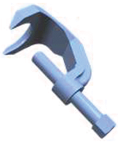
CH-43631
J-43631
Ball Joint Remover
READ NEXT:
 Suspension General Diagnosis
SPECIFICATIONS
TRIM HEIGHT SPECIFICATIONS
Trim Height Specifications (P-R Height) - Hatchback
NOTE: For 0% option vehicles add 1 mm to front and rear suspension
values.
For 100% option vehicles subt
Tire Pressure Monitoring System
SPECIFICATIONS
FASTENER SPECIFICATIONS
Reusable Threaded Fastener Tightening Specifications
NOTE:
All fasteners listed in this table can be reused after removal.
SEE MORE:
Power Door Locks
Touch and the following may
display:
Open Door Anti Lockout
Auto Door Unlock
Delayed Door Lock
Open Door Anti Lock Out
When on, this feature will keep the
driver door from locking when the
door is open. If Off is selected, the
Delayed Door Lock menu will be
available.
Touch Off or On.
Auto Doo
Power Transfer Unit Cover To Intermediate Drive Shaft Seal Replacement
Special Tools
DT-305-1 Driver Handle
DT-51466 Seal Installer
Equivalent regional tools: Special Tools
Removal Procedure
1. Raise and support the vehicle. Lifting and Jacking the Vehicle.
NOTE: The drive shaft remains in the wheel hub.
2. Front Wheel Drive Half Shaft- Right Side@Transfer Case - D
© 2019-2025 Copyright www.buregal6.com
