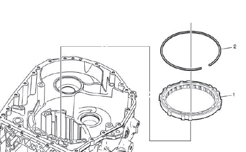
Buick Regal: Low and Reverse Clutch Piston Installation
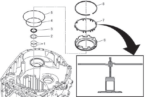
- Direct Clutch Fluid Seal Ring [2x]
- Direct Clutch Hub Thrust Bearing Race
- 2nd Clutch Housing Rear Bearing
- Low and Reverse Clutch Application Ring
- Low and Reverse Clutch Application Ring
- Low and Reverse Clutch Piston
- 1-Reverse Clutch Spring
- 1-Reverse Clutch Spring Retaining Ring
Procedure
Using the DT-48056 bridge with DT-48903 and DT-51920 compressors, install the retaining ring.
NOTE: Ensure DT-51920 Clutch Spring Compressor is clocked properly and only making contact with the 1-Reverse clutch spring.
Special Tools
- DT-48056 Spring Compressor Bridge
- DT-48903 Spring Compressor
- DT-51920 Clutch Spring Compressor
Equivalent regional tools: Refer to Special Tools
DIRECT CLUTCH ASSEMBLY INSTALLATION
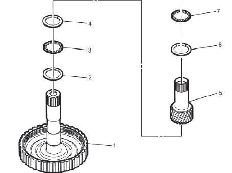
- Direct Clutch
- Direct Clutch Hub Thrust Bearing Race
- Direct Clutch Bearing
- Rear Sun Gear Thrust Bearing Race
- Rear Sun Gear
- Rear Sun Gear Thrust Bearing Race
- Rear Sun Gear Thrust Bearing
REAR CARRIER INSTALLATION
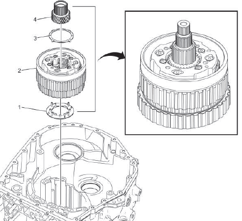
- Rear Carrier Thrust Washer
- Rear Carrier
Procedure
- Assemble this on the table with Direct Clutch Assembly Installation.
- Rotate till seated completely.
- Install complete direct clutch and rear carrier assembly as a unit.
- Rear Carrier Thrust Washer
- Sun Gear
1ST AND REVERSE CLUTCH BACKING PLATE INSTALLATION
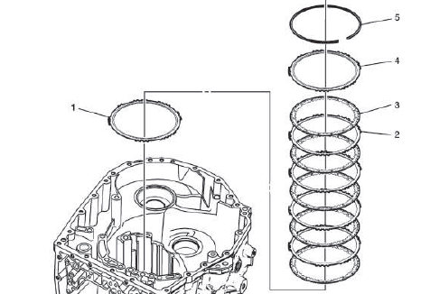
- 1st and Reverse Clutch Backing Plate
NOTE: Machined side down.
- 1st and Reverse Clutch Plate
- 1st and Reverse Clutch Plate - Friction Plate
- Forward Clutch Backing Plate
NOTE: Groove up to accept the retaining ring.
- 1-Reverse Clutch Backing Plate Retaining Ring
OVERRUN CLUTCH INSTALLATION
- Overrun Clutch
NOTE: Rotate the rear carrier clockwise while installing.
- Overrun Clutch Retaining Ring
NOTE: Rotate the rear carrier clockwise until fully seated to accept retaining ring.
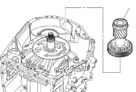
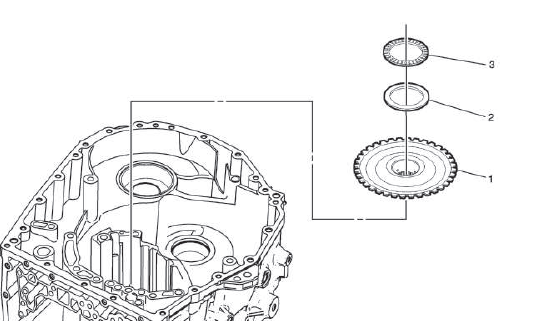
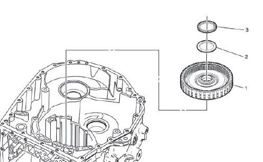
COUNTER DRIVE GEAR INSTALLATION
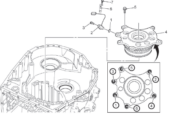
Fig. 3: Automatic Transmission Counter Drive Gear Bolts Tightening Sequence
- Vehicle Speed Sensor Spacer
- Vehicle Speed Sensor
- Automatic Transmission Intermediate Speed Sensor Bolt
CAUTION: Refer to Fastener Caution.
Tighten 5 N.m (44 lb in)
- Counter Drive Gear
- Center Support Bolt[6x]
Tighten in sequence 62 N.m (46 lb ft)
- Automatic Transmission Control Wiring Harness Clamp
- Front Differential Transfer Drive Gear Fluid Passage Tube Bolt
Tighten 7 N.m (62 lb in)
FINAL DRIVE PINION AND RING GEAR INSTALLATION
- Final Drive Pinion and Ring Gear
MANUAL SHIFT DETENT LEVER AND PARK PAWL INSTALLATION
Lubricant Fluid Pipe Installation

- Automatic Transmission Vent Baffle Cover
- Torque Converter and Differential Housing Bolt
CAUTION: Refer to Fastener Caution.
Tighten 7 N.m (62 lb in)
- Automatic Transmission Vent Baffle Cover
- Torque Converter and Differential Housing Bolt
Tighten 7 N.m (62 lb in)
- Lubricant Fluid Pipe
- Lubricant Fluid Pipe Retainer
- Automatic Transmission Control Wiring Harness Clamp
- Front Differential Transfer Drive Gear Fluid Passage Tube Bolt [2x]
Tighten 7 N.m (62 lb in)
Park Components Installation
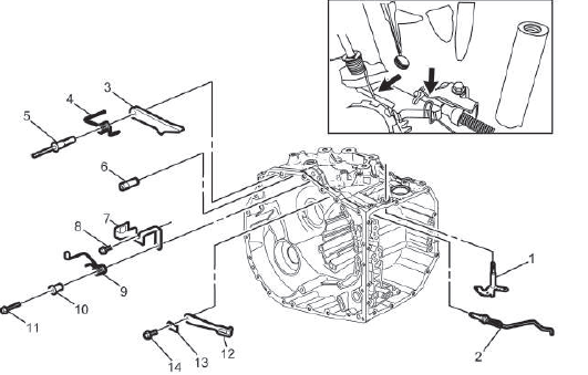
- Manual Shift Shaft Lever
- Park Pawl Actuator Rod
NOTE: Rotate the manual shift shaft lever to get rod in place.
- Park Pawl
- Park Pawl Spring
NOTE: Ensure spring is in proper location like the inset shows.
- Park Pawl Shaft
- Park Pawl Lockout Pin
- Park Pawl Actuator Bracket
NOTE: Ensure park pawl actuator rod is in proper location like the inset shows before tightening the bolts.
- Park Pawl Actuator Bracket Bolt
CAUTION: Refer to Fastener Caution.
Tighten 9 N.m (80 lb in)
- Park Pawl Pin Spring Guide Sleeve
- Park Pawl Actuator Lever Spring
NOTE: Ensure Spring is in proper location like the inset shows.
- Park Pawl Actuator Bracket Bolt
Tighten 9 N.m (80 lb in)
- Manual Shift Detent Lever Spring
- Automatic Transmission Control Lever Detent Spring
- Manual Shift Detent Bolt
Tighten 10 N.m (89 lb in)
INPUT DRUM INSTALLATION
- Input Drum
- Sun Gear Front Thrust Bearing Race
- Input Sun Gear Thrust Bearing
FORWARD CLUTCH ASSEMBLY INSTALLATION
- Forward Clutch
- Forward Clutch Housing Thrust Bearing Race
- Input Clutch Housing Thrust Bearing
READ NEXT:
 Front Internal Gear Installation
Input Carrier Flange
Forward Clutch Backing Plate Retaining Ring
Front Internal Gear
NOTE:
Rotate to index the clutch plate and ensure seated.
Front Carrier Thrust Bearing
Front Carrier T
Torque Converter and Differential Housing Assembly Assemble
Front Differential Transfer Drive Gear Fluid Passage Tube
Lubricant Fluid Hose Clamp
Automatic Transmission Fluid Baffle Bolt
CAUTION: Refer to Fastener Caution.
Tighten
7 N.m (62 lb in)
SEE MORE:
Specifications, Diagnostic Information and Procedures
SPECIFICATIONS
FASTENER SPECIFICATIONS
Single Use Non-Threaded Fasteners/Components
NOTE:
All fasteners/components listed in this table MUST BE DISCARDED and replaced
with NEW
after removal.
Application
O-Ring at PTU Output Shaft
O-Ring at Rear Differential Input Shaft
Retaining Ring at PTU Output
Engine Front Cover Removal
1.
Remove the accessory drive belt tensioner bolt (1).
2. Remove the accessory drive belt tensioner (2).
3.
Remove the engine front cover bolts (2 - 7, 9).
4. Discard bolts 3, 5, and 6.
5. Remove the engine front cover (1).
6. Ensure proper use of room temperature vulcanizing (RTV) sealant. U
